Hydraulic Servo-Proportional Control Systems – Achieving Sub-Micron Repeatability in CNC Press Brake Cylinders
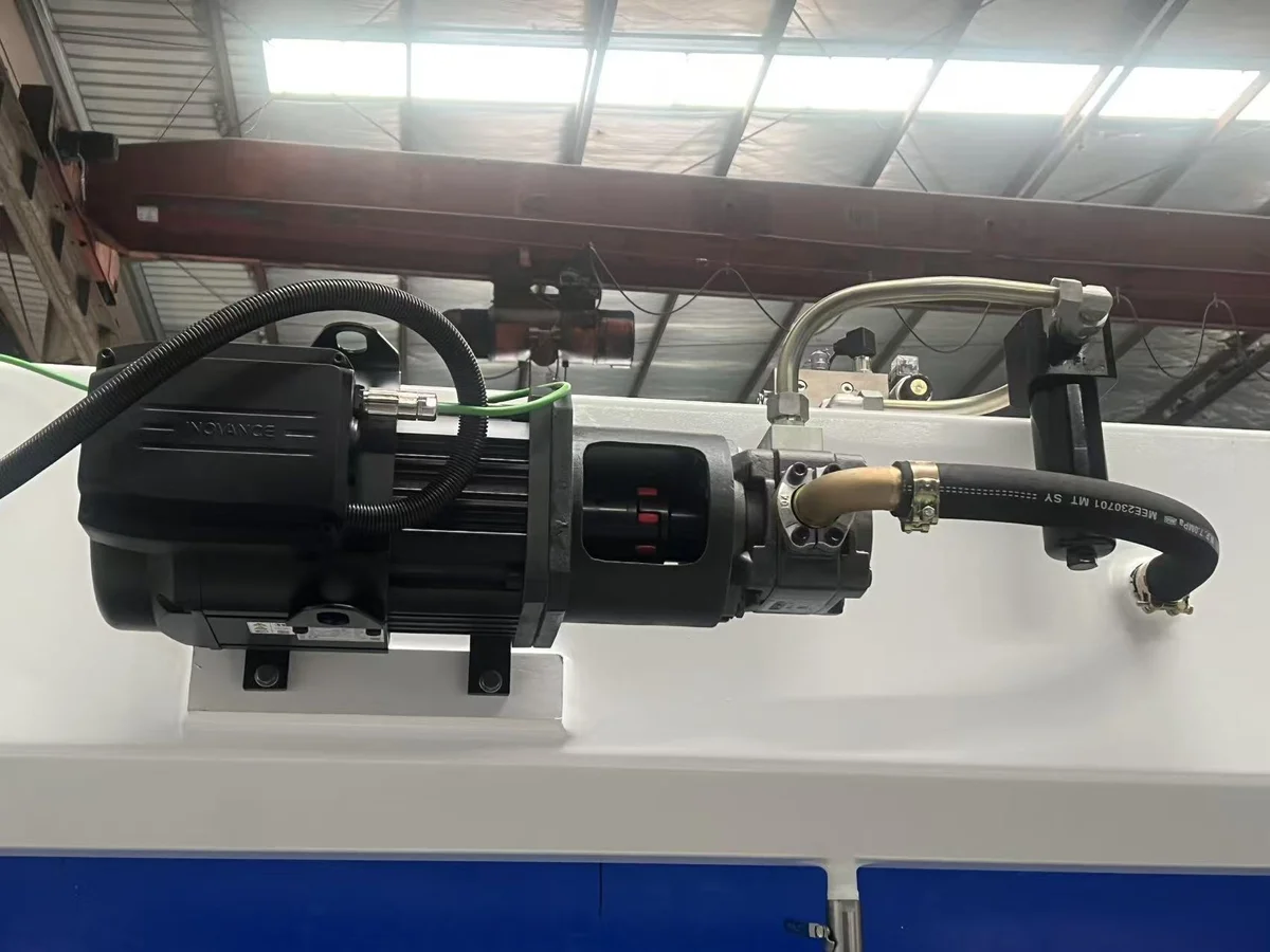
Precision CNC bending requires micro-second oil flow adjustments. This article explains the feedback loops, linear encoders, and proportional valves of modern press brakes.
The primary challenge in manufacturing high-precision sheet metal parts is maintaining consistency. A variation of even 0.01 mm in the final position of the upper beam (ram) can alter the bend angle of a thin sheet by up to 0.5°.
To maintain angle consistency across thousands of parts, a modern CNC press brake must control cylinder position with sub-micron repeatability. This is achieved using dual closed-loop hydraulic servo-proportional control systems.
The Closed-Loop Feedback Architecture
A servo-hydraulic press brake controls the motion of the upper beam (Y1 and Y2 axes) using two independent hydraulic cylinders. To keep the beam level and accurate, the machine uses a real-time closed-loop control circuit.
CNC Controller
Servo Proportional Valve A
Hydraulic Cylinder Y1
Linear Encoder Y1 (1µm resolution)
Servo Proportional Valve B
Hydraulic Cylinder Y2
Linear Encoder Y2 (1µm resolution)
- Command Generation: The operator sets the target angle. The CNC controller calculates the target position for the Y1 (left) and Y2 (right) cylinders.
- Position Measurement: High-resolution linear encoders (mounted on independent C-frames to isolate them from frame deflection) measure the exact position of both cylinder pistons to within 0.001 mm.
- Real-Time Correction: The controller compares the actual positions of Y1/Y2 with the target path. If it detects a deviation (e.g., if one side is lagging by 0.005 mm), it adjusts the command signal to the corresponding servo-proportional valve.
- Flow Regulation: The proportional valves adjust their opening area within milliseconds, regulating oil flow to each cylinder to bring the beam back into alignment.
Proportional Valves vs. Standard On/Off Valves
To help fabrication shops understand the technology behind precision bending, the table below highlights the performance differences between servo-proportional valve systems and standard hydraulic press controls:
| Technical Parameter | Standard Hydraulic Control | RAXMEK Proportional Servo Control |
|---|---|---|
| Piston Position Repeatability | ±0.1 mm to ±0.2 mm | ±0.005 mm (5 microns) |
| Response Time | Slow (mechanical limit valves) | Extremely Fast (< 10 milliseconds) |
| Synchronized Levelling | Mechanical torsion bar | Independent electronic closed-loop |
| Off-Center Bending Capability | None (causes frame twist / tool damage) | High (valves automatically balance offset load) |
| Stroke Profile Tuning | Fixed speeds | Adjustable fast-approach, bending, and return speeds |
| Energy Consumption | Constant pump bypass heating | On-demand pressure control (reduces energy use) |
Mechanics of Off-Center Bending
When a sheet is bent off-center (on one side of the bed), it generates an unbalanced load. On older torsion-bar press brakes, this off-center load causes the upper beam to twist, leading to angle errors and potential frame damage.
On a servo-proportional CNC press brake, the Y1 and Y2 cylinders operate independently. When the sheet is bent on the left side, the left cylinder (Y1) encounters higher resistance and lags slightly.
The linear encoder instantly detects this lag. The CNC controller then throttles the oil flow to the right cylinder (Y2) and increases pressure to the left cylinder (Y1), maintaining beam alignment under off-center loads.
Operational Maintenance of Servo-Hydraulic Systems
High-performance servo-proportional valves operate with extremely tight mechanical clearances (often less than 2 to 4 microns). This makes them highly sensitive to hydraulic fluid contamination.
1. High-Performance Fluid Filtration
To protect proportional valves, systems must include pressure-line filters (rated at 3 microns) in addition to standard return filters. Operating oil must be analyzed regularly to ensure it meets ISO 4406 15/13/10 cleanliness standards.
2. Proactive Oil Temperature Control
High-frequency valve adjustments generate heat. If oil temperature exceeds 55°C, its viscosity drops, leading to increased valve leakage and reduced positioning accuracy. Press brakes should be configured with active oil coolers (air or water-based) to keep operating temperatures within the optimal 40°C to 48°C range.
Engineering Support and Technical Consultation
At RAXMEK, we engineer our CNC press brakes with Finite Element Method (FEM) optimized frames, high-precision linear encoders, and premium Hoerbiger or Rexroth hydraulic manifolds.
Our engineering team is ready to help you optimize your bending operations. We offer:
- Custom Control Tuning: Designing specialized bending speed profiles for delicate or springy alloys.
- System Upgrades: Configuring high-speed backgauge options (up to 6 axes) and active sheet thickness measurement integrations.
- Detailed Quotations: Complete technical descriptions, shipping details, and operator training packages.
Contact RAXMEK today to speak with a technical expert and improve your production accuracy.
Похожие ресурсы
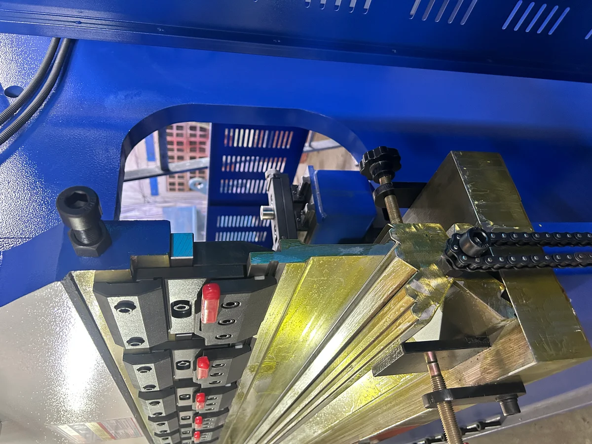
CNC Press Brake Crowning Systems – Hydraulic vs. Mechanical Deflection Compensation for High-Precision Metal Bending
In precision sheet metal bending, frame deflection directly affects angle consistency across the bending length. This article examines the mechanical differences, PID feedback...
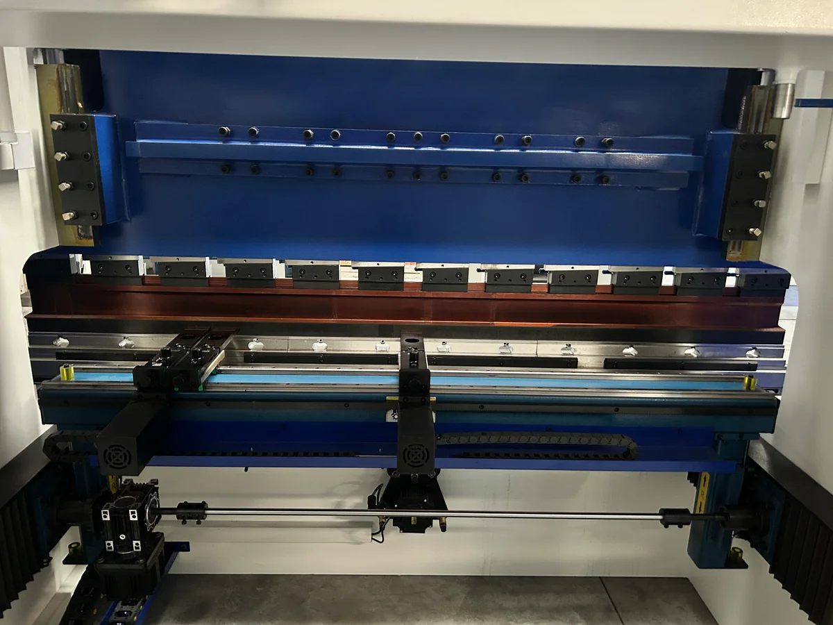
CNC Press Brake Backgauge Systems – Comparing Multi-Axis (X, R, Z1, Z2, X1, X2) Drive Configurations and Their Impact on Bending Accuracy
A deep dive into press brake backgauge axes, drive kinematics, and linear transmission systems. Learn how multi-axis (X, R, Z1, Z2, X1, X2) setups improve production speed...
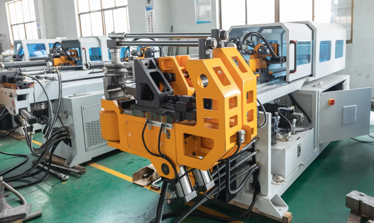
Mandrel Selection and Placement Kinematics – Preventing Wrinkling, Ovality, and Wall Thinning in Thin-Walled Tube Bending
High-quality tube bending requires careful management of internal and external forces. This article explores mandrel types, wiper die settings, and mandrel insertion depth...