Mandrel Selection and Placement Kinematics – Preventing Wrinkling, Ovality, and Wall Thinning in Thin-Walled Tube Bending
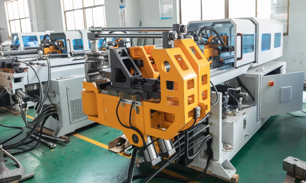
High-quality tube bending requires careful management of internal and external forces. This article explores mandrel types, wiper die settings, and mandrel insertion depth calculations.
Bending thin-walled tubes to tight radii is one of the most difficult processes in metal fabrication. Without internal support, the bending force causes the tube cross-section to collapse, leading to three common defects:
- Wrinkling: Folds forming on the inside radius due to compressive stress.
- Ovality: The outer profile flattening into an oval shape instead of remaining round.
- Wall Thinning: The outer wall stretching and thinning, which can lead to cracks or structural failure under high fluid pressure.
To prevent these defects and maintain roundness, high-precision operations employ mandrels and wiper dies.
Mandrel Types and Applications
A mandrel is an internal support tool inserted into the tube at the bend point. The choice of mandrel depends on the tube’s wall thickness and the severity of the bend, which is determined by the Wall Factor (Tube Outer Diameter divided by Wall Thickness, $D/t$) and the Bend Severity (Center-line Radius divided by Outer Diameter, $CLR/D$).
Spoon / Plug Mandrel
A solid steel support tool featuring a curved, spoon-like or plug end. Positioned directly at the tangent point of the bend to prevent external wall collapse.
Ideal for: Thick-Walled Tubes & Gentle Bends
Linked Ball Mandrel
Features a solid steel shank linked to a series of pivoting spherical balls. The balls flex dynamically with the inner tube contour to support thin walls under strain.
Ideal for: Thin-Walled Tubes & Severe Bends
1. Plug and Spoon Mandrels
Solid, rigid mandrels used for thick-walled tubes or gentle bends. They provide simple support at the tangent point to prevent the outer wall from collapsing.
2. Ball Mandrels
Consist of a solid shank connected to a series of flexible, pivoting ball segments that extend past the bend tangent point. The balls flex with the tube during the bend, supporting the inner profile over a longer arc. Ball mandrels are divided into standard and thin-wall configurations (which have tighter linkages to support very thin sheets).
Wiper Die Function and Placement
While mandrels support the tube from the inside, a wiper die supports it from the outside on the inner bend radius. During bending, compressive forces push material back, which can cause wrinkles. The wiper die features a sharp, feathered edge positioned precisely at the tangent point. It acts as a guide, scraping the material smooth as it flows into the bend and preventing wrinkle formation.
Mandrel Placement and Thinning Calculations
1. Calculating Mandrel Insertion Depth (Tangent Point)
For a mandrel to work effectively, the lead edge of the mandrel body (the “tangent point”) must be positioned slightly ahead of the point where the bend begins. If the mandrel is placed too far forward, the tube will bulge or split on the outer wall. If it is too far back, the inner wall will wrinkle. The optimal mandrel setting ($S_m$) is calculated relative to the tube outer diameter ($D$) and center-line radius ($R$):
Sm = (D × R) / (2 × CLR) + c
Sm: Mandrel projection past tangent (mm)
D: Tube outer diameter (mm)
CLR: Center-line bend radius (mm)
c: Material correction constant (0.5 to 1.5)
2. Wall Thinning Ratio
During bending, the outer wall of the tube stretches, reducing its thickness. Engineers calculate the expected thinning ratio ($T_r$) to ensure the tube remains strong enough for pressure ratings (e.g., in hydraulic or boiler tubes). The thinning ratio is defined by:
T_r = 1 - CLR / (CLR + 0.5 × D)
For a 50 mm tube bent on a 75 mm CLR, the thinning ratio is approximately 25%. If the original wall thickness was 2.0 mm, the outer wall will thin to 1.5 mm after bending.
Troubleshooting Guide for Tube Bending Defects
To help shop floor supervisors and quality control teams quickly resolve bending issues, refer to the troubleshooting matrix below:
| Observed Defect | Primary Mechanical Cause | Recommended Adjustment |
|---|---|---|
| Wrinkles on inside bend | Inadequate wiper die support or loose mandrel fit | Advance wiper die closer to tangent; increase mandrel size or add ball segments |
| Cracking / splitting on outside bend | Mandrel positioned too far forward or insufficient lubrication | Retract mandrel slightly; check pressure die boost speed; use high-viscosity bending oil |
| Heavy ovality / flattening | Mandrel too far back or no mandrel used | Advance mandrel forward; verify mandrel clearance fits within 0.1 mm of tube ID |
| Hump at end of bend | Mandrel balls retracting too late or incorrect link slack | Adjust CNC mandrel retract timing; tighten ball link joints |
| Wiper die tearing / wearing quickly | Incorrect rake angle or lack of lubrication | Check wiper die alignment; increase lubricant flow; use bronze-alloy wiper for stainless steel |
B2B Operational and Maintenance Strategy
For industrial manufacturers, setting up a tube bending cell requires looking at total consumable and downtime costs.
1. Tooling Material Compatibility
Using the wrong mandrel material can lead to galling, scrap parts, and rapid tool wear. For carbon steel tubes, tool-steel or hard-chromed mandrels are ideal. However, for stainless steel or titanium bending, aluminum-bronze or plated copper-alloy mandrels must be used to prevent friction-induced welding and surface scratching.
2. Automatic Mandrel Lubrication
High friction during mandrel bending heats the tools, causing them to expand and wear out quickly. RAXMEK CNC pipe benders feature an automatic through-mandrel lubrication system that injects a metered dose of high-viscosity lubricant directly through the mandrel shaft and out of holes in the mandrel body during each bend cycle. This reduces tool wear by 60% and keeps the inner tube walls clean.
Technical Consultation and Engineering Support
At RAXMEK, we engineer our CNC pipe bending machinery with heavy gantry frames, high-accuracy servo-electric bending arms, and precise mandrel extractor cylinders to handle heavy-duty production.
Our engineering support team is ready to help you configure your tooling setup. We provide:
- Tooling Audits: Reviewing your tube drawings to calculate Wall Factors, Bend Severity, and recommending the optimal mandrel/wiper die setup.
- Lubricant Testing: Recommending the ideal bending gel or oil for your specific material grade (carbon steel, stainless, or titanium).
- Custom Tooling Packages: Providing custom-ground bend dies and multi-ball mandrels for specialty tube sections.
Contact RAXMEK today to speak with a technical expert and improve your bending precision.
الموارد ذات الصلة
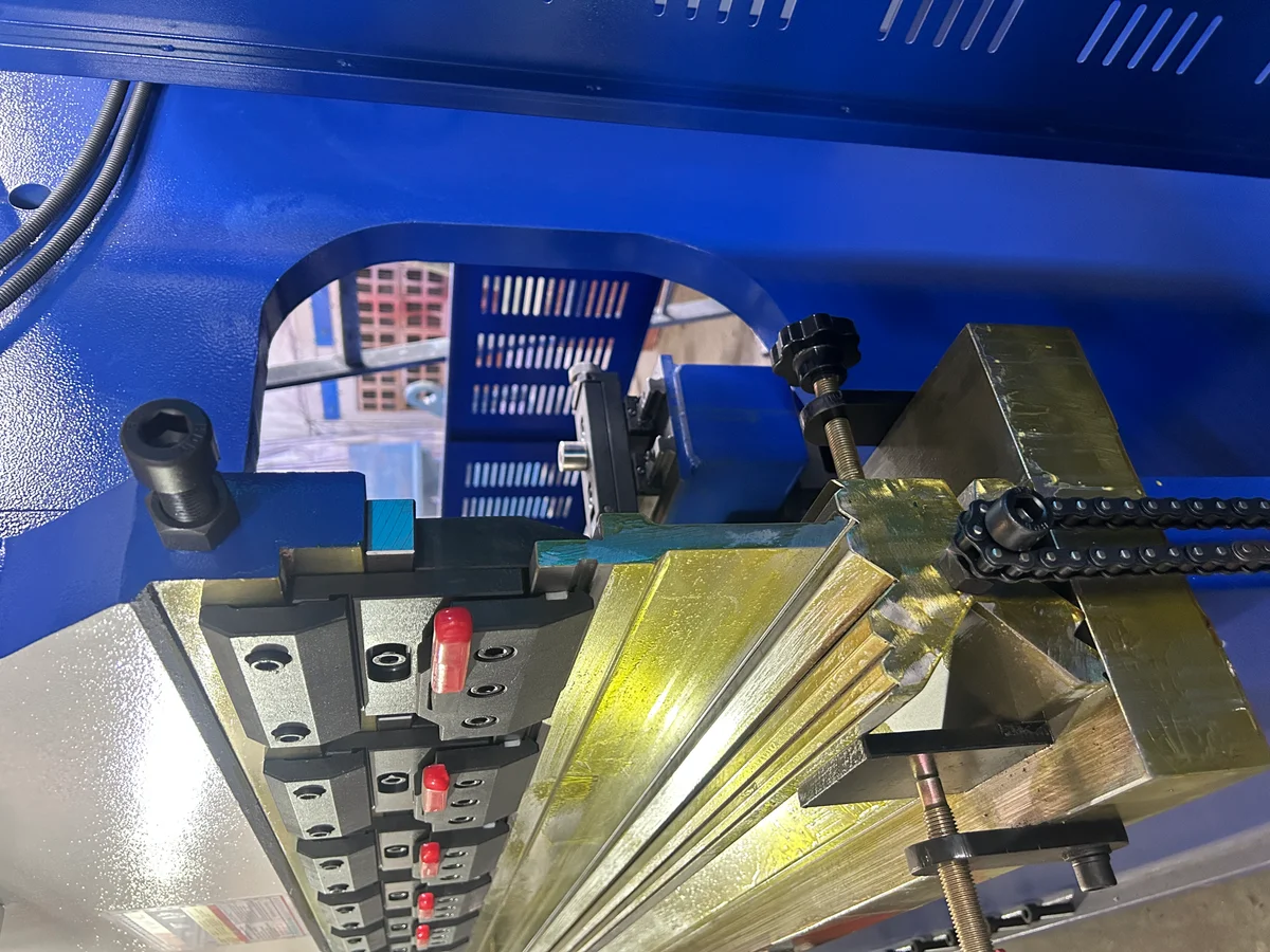
CNC Press Brake Crowning Systems – Hydraulic vs. Mechanical Deflection Compensation for High-Precision Metal Bending
In precision sheet metal bending, frame deflection directly affects angle consistency across the bending length. This article examines the mechanical differences, PID feedback...
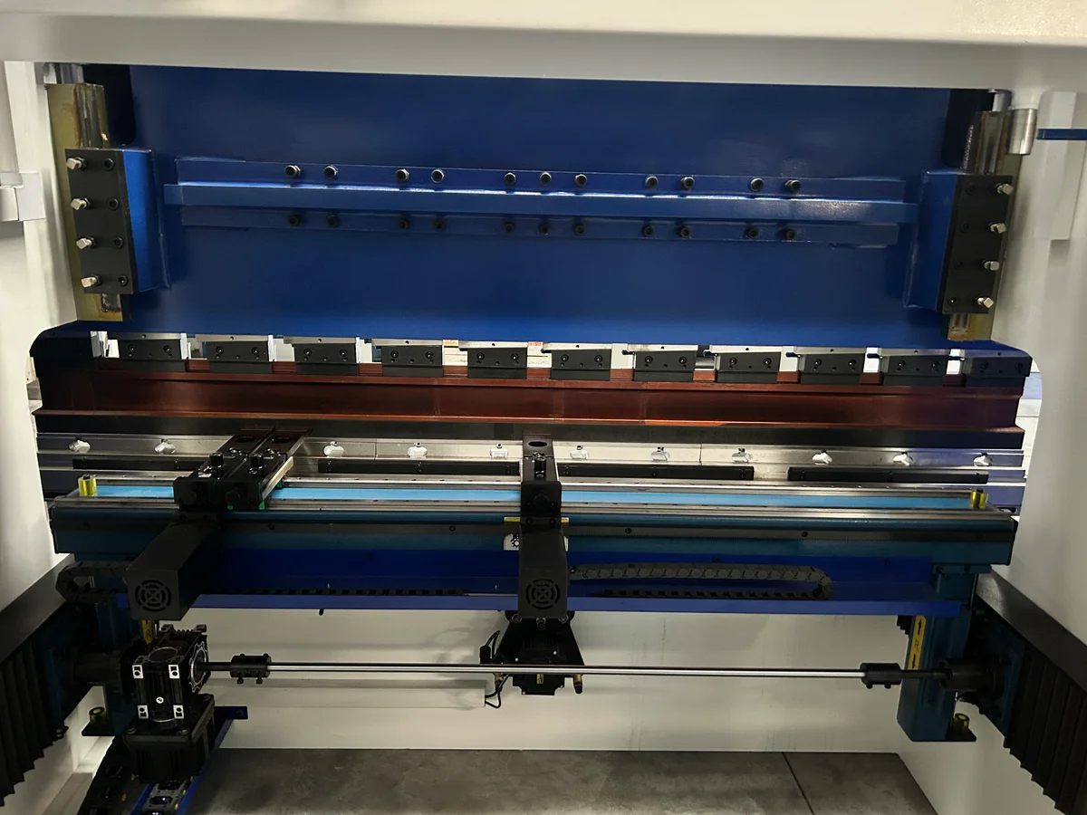
CNC Press Brake Backgauge Systems – Comparing Multi-Axis (X, R, Z1, Z2, X1, X2) Drive Configurations and Their Impact on Bending Accuracy
A deep dive into press brake backgauge axes, drive kinematics, and linear transmission systems. Learn how multi-axis (X, R, Z1, Z2, X1, X2) setups improve production speed...
Punch-to-Die Clearance Kinematics in CNC Punching – Preventing Burr Formation, Tool Wear, and Frame Deflection
Selecting the correct clearance between the punch and die is critical for hole quality and tool life. This article explains the mechanics of metal shearing, clearance calculations...